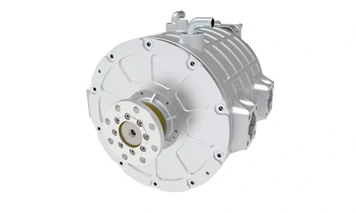
Working principle of the motor
New energy vehicle drive motors generally include DC motors, asynchronous motors, permanent magnet synchronous motors and switched reluctance motors. Among them, DC motors are the simplest to control, but the product reliability is poor, and they are generally used in low-speed vehicles. Asynchronous motors are also widely used due to their high reliability and low cost. Permanent magnet synchronous motors are currently the mainstream product due to their advantages of high efficiency and high power density. Switched reluctance motors have the highest product reliability and the lowest cost, and are the future development direction (due to technical reasons such as large torque fluctuations, high noise and control algorithms, they have not yet been popularized).
The permanent magnet synchronous motor rotor has its own permanent magnet and does not require electrical excitation. When a symmetrical three-phase current is passed through the stator winding of the motor, a rotating stator magnetic field is generated. The rotating stator magnetic field interacts with the rotor magnetic field to generate an axial torque, driving the rotor to rotate.
(1) The permanent magnet acts as a rotor to generate a rotating magnetic field.
(2) The three-phase winding is connected to a three-phase sinusoidal symmetrical current with a spatial phase difference of 120° to generate a rotating magnetic field.
(3) The magnetic fields of the stator and rotor interact to generate torque, and electrical energy is converted into kinetic energy.


Main structure of the motor
1. Permanent magnet synchronous motors are important actuators of the power system and are elements for converting electrical energy and mechanical energy. Their operating status can be collected in the MCU.
2. Built-in sensors are used to provide motor working information
(1) The rotary transformer is used to detect the position of the motor rotor, and the microcontroller decodes it to obtain the motor speed signal
(2) The temperature sensor is used to detect the temperature of the motor winding. The microcontroller can prevent the motor from overheating.
The driving motors used in our company’s new energy vehicles are mainly permanent magnet synchronous motors. The motor structure is mainly composed of a permanent magnet rotor assembly, a stator assembly, a front and rear end, and a rear end cover. In addition to the above four major components, there are also low-voltage detection parts and other structural parts.


Key indicators for motor selection
Voltage platform: mainly related to battery selection, affects motor output power
Rated torque @ rated speed, long-term operation
Continuous power:
Peak power: peak torque @ peak power (usually the inflection point of the motor’s external characteristic curve), short-term operation
Peak current: the maximum current required for the motor to output peak torque, related to the electronic control IGBT, commonly used
Modules 600A, 800A, 900A, etc., converted to the AC side of the motor, divided by 1.414
That is, the maximum peak current (AC effective value) input to the motor, generally
There will be a certain margin, such as 600A:4=424A, and 400A is actually used;
No-load back EMF: generally expressed in VDC (direct current), which will affect the selection of electronic control IGBT, such as the commonly used
1200V, the maximum speed no-load back EMF of the motor is generally required not to exceed 1050:


